Linear positioning axes are used as basic assemblies in a wide range of applications in manufacturing, measuring and instrumentation technology, such as in machine tools and coordinate measuring machines. This results in a wide range of positioning ranges and accuracy requirements depending on the application.
When linear axes are installed in machines and devices, the accuracy of the overall system is limited by all rotational and translational deviations of the individual axes from the ideal linear path of motion (see Figure 1). These deviations are properties of the linear axes themselves, but are also determined by their mounting position. For manufacturers of machines and equipment alignment of the axes is absolutely necessary when mounting the system.
The highly accurate, dynamic detection of the guiding properties during the adjustment and alignment of the system components is consequently key to achieving minimum positioning deviations of the system.
Setup and features of the measuring systems
The devices for alignment and calibration of linear axes presented here are based on laser interferometric measuring methods [3,4]. They allow the highly accurate simultaneous acquisition of the linear position, the pitch and yaw angle as well as a straightness component in a single measuring run. The measurement of the second straightness component is easily and quickly done by rotating the straightness mirror the straightness mirror and a prism in the reflector unit by 90°.
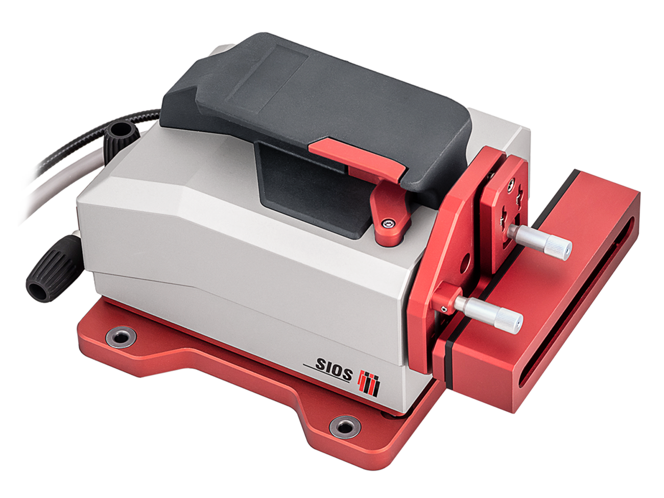
The measurement system consists of a fiber-coupled sensor head, a reflector unit and a spatially separated supply and evaluation unit containing fiber-coupled laser and electronics. The sensor head of the calibration laser interferometer contains the interferometer optics for three independent length measurement channels for determining linear position, pitch and yaw angle, in addition to another interferometer channel for detecting horizontal and vertical straightness.
The measuring resolution of the interferometric length measurement is 0.00002 µm over a measuring range of up to 50 m. The measuring range of the straightness measurement is ±4 mm, with a measuring resolution of 0.01 µm.
The reflector unit is a combination of three retroreflectors for length and angle measurement and a Wollaston prism for straightness measurement. The use of triple mirror retroreflectors allows a maximum tilt angle of the reflector unit of more than ± 5°. The three retroreflectors are spaced 50mm apart. The large base distance in combination with the high interferometric length resolution results in an angular measurement resolution of 0.0004 angular seconds.
Calibration and alignment of linear axes
The aim of acceptance measurements and calibrations on linear axes is to record the actual condition with the corresponding deviations for position, pitch and yaw angles and straightness. Acceptance measurements are documented (e.g. according to VDI/DGQ 3441, DIN ISO 230 or VDI 2617 with InfasAXIS). In the case of calibrations, the data obtained is used to make corrections. In both cases, the measurement is typically performed by measuring from different positions along the traverse range and recording the guiding deviations. The measurement can be triggered by signals from the machine control system, manually or by standstill detection. Here, multi axis systems are an advantage because they allow mutual assignment (including random portions) of the guideway deviations in addition to reducing the required measuring times.
The alignment of linear axes, on the other hand, is a dynamic process in which measurement and intervention on the system (e.g. changing the screw connection at the bearing point) alternate. It is therefore necessary to record the existing guideway deviations within seconds. Measurement data processing must immediately provide a display to be used for alignment and adjustment. Furthermore, it cannot be assumed that the linear axis will have positioning drives or position measuring systems at the time of adjustment, so that measurements cannot be taken at defined measuring positions.
The measuring systems presented here are suitable for such alignment tasks. The simultaneous displacement and angle measurement enables angular and straightness values of the guide to be measured relative to position. The guide can be moved manually for this purpose. The values for the traveled guideway distance along the guideway are displayed immediately. Due to the large measuring ranges the measuring system is robust even with alignment against interventions on the linear axis.
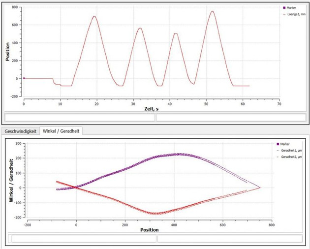
Figure 2 shows the display of the InfasALIGN measuring software during a machine alignment. The upper window shows the position along the guide over time. The guide slide was moved back and forth several times, covering both parts and the complete displacement range of the guide. The lower window shows the measured guide deviations compared to the position along guide. The angles, the straightness based on the angle measurement and the straightness by means of Wollaston can be displayed either individually or together.
Abstract
The use as a measuring system for the adjustment and alignment of linear axes is possible due to the dynamic and simultaneous recording of the measured variables where the user is supported by the highly accurate recording and immediate display of the guideway deviations. A single system can be used for alignment, calibration and acceptance.
The Calibration Laser Interferometers allow position measurements up to 50 m, with an accuracy of 1⋅10-7 based on environmental measurement data acquisition characteristics. Simultaneous measurement of multiple degrees of freedom reduces the required measurement time for acceptance, calibration and system analysis.

Calibration laser interferometer
up to 6 DoF calibration of axes and linear guides
![[Translate to Englisch:] Kalibrierung von Linearachsen [Translate to Englisch:] Grafische Darstellung zur Kalibrierung von Linearachsen simultane Erfassung von 5-DOF](/fileadmin/user_upload/Anwendungen/01-calibration-interferometer-linear-axis.jpg)


